
SUNLED Lighting: Your Premier PCBA Board Manufacturer!
Shenzhen SUNLED Lighting Co., Ltd. was established in November 2012. It is an enterprise integrating R&D, production and trade. It mainly produces LED lighting products.
Highly Efficient Production
We have independent factories for product production. The company's production department has 30-50 employees, and has 4 complete production lines, 4 placement machines and a complete set of LED testing equipment. The daily output of LED products reaches 20,000 pieces.
Strong R&D Capabilities
We have a R&D team composed of several senior engineers in the LED industry, focusing on the improvement of existing products and the development of new LED products. We can not only provide customers with solutions but also customize LED products according to requirements.
High Quality Guarantee
In terms of raw materials, we mainly use chips imported from Taiwan, and the quality of every product we produce meets customer requirements. Our products are produced under a strict quality control system, the defective rate will be less than 0.2%, and the products are provided with a 2-5 year warranty.
Fast Delivery
It only takes 3-5 days for us to produce samples, and only 1-2 weeks for mass production. We can quickly package and send the finished products to you. We have cooperated with international logistics companies such as DHL, UPS, FedEx and TNT, and can deliver products to all parts of the world on time.
-
![8W 12W LED square PCB Board]() 8W 12W LED square PCB BoardSquare Light Panel It is a kind of lighting equipment with a square shape as the main body, generally composed of a light box, a light base, a light bulb, and auxiliary materials. Square light panels are widely used indoors, outdoors, squares, corridors and other places. Generally, LED light...view more
8W 12W LED square PCB BoardSquare Light Panel It is a kind of lighting equipment with a square shape as the main body, generally composed of a light box, a light base, a light bulb, and auxiliary materials. Square light panels are widely used indoors, outdoors, squares, corridors and other places. Generally, LED light...view more

What is PCBA Board?
A printed circuit board assembly(PCBA) is an electronic assembly that uses copper conductors to create electrical connections between components. PCBAs also provide mechanical support for electronic components so that a device can be mounted in an enclosure.
All PCBAs are built from alternating layers of conductive copper with layers of electrically insulating material. Conductive features on printed circuit boards include copper traces, pads, and conductive planes. The mechanical structure is made up of the insulating material laminated between the layers of conductors. The overall structure is plated and covered with a non-conductive solder mask, and silk screen is printed on top of the solder mask to provide a legend for electronic components. After these fabrication steps are completed, the bare board is sent into printed circuit board assembly, where components are soldered to the board and the PCBA can be tested.

Printed circuit boards are used for a variety of purposes. One distinguishing characteristic of PCBAs is their class–either 1, 2, or 3. The class of PCBA indicates its overall reliability and quality of design.
● Class 1 boards designate a consumer electronic.
● Class 2 boards are found in devices where high reliability is important, but not crucial. These devices try to minimize failure.
● Class 3 boards represent the most exacting manufacturing standards of a PCBA. Simply put, if a Class 3 board fails, lives are immediately at stake–for example, the boards on an airplane.
Types of Printed Circuit Boards
Single Sided PCBA Substrate
The single layer is on an insulating substrate with a thickness of 0.2-5mm, only one surface is covered with copper foil, and a printed circuit is formed on the substrate by printing and etching. The single panel is simple to manufacture and easy to assemble. It is suitable for the requirements of a circuit, such as radios, televisions, etc.It is not suitable for occasions requiring high assembly density or complex circuits.
Double Sided PCBA Substrate
The double sided boards are printed circuits on both sides of an insulating substrate with a thickness of 0.2-5mm. It is suitable for electronic products with general requirements, such as electronic computers, electronic instruments and meters. Since the wiring density of the double-sided printed circuit is higher than that of the single-sided printed circuit, the volume of the device can be reduced.
Multilayer PCBA Plate
Printed panel with more than 3 layers of printed circuits printed on an insulating substrate are called multilayer panel. It is a combination of several thin single or double panels, and its thickness is generally 1.2-2.5mm. In order to lead out the circuit sandwiched between the insulating substrate, the holes for mounting components on the multilayer board need to be metalized, that is, a metal layer is applied to the inner surface of the small holes to connect them with the printed circuit sandwiched between the insulating substrates.
Flex PCBAs
Flexible printed circuit boards are a rising favorite due to their ability to be bent, twisted, or folded to fit their electronic device. Rather than placing printed circuits and electronic components on a rigid substrate, these elements are placed on a flexible one - mostly a conductive polyester film. Flex PCBAs can be single- or double-sided as well as multi-layered. These boards are often used in automotive applications, medical devices, and cameras.
Rigid PCBAs
Rigid PCBAs feature an inflexible substrate and cannot be twisted, bent, or folded. Oftentimes these lightweight and cost-effective boards are made with numerous layers, including a substrate, conductive, solder mask, and silk screen layer. Rigid PCBAs can be single or double sided, or multi-layered. They are typically used in X-ray machines, MRI systems, and GPS equipment.
Rigid-Flex PCBAs
These hybrid PCBAs feature the best of both worlds. Flexible yet rigid, these circuit boards are designed and built in 3D. This enables them to be tailor-made for the device in which they’ll be used. Rigid-flex PCBAs are also lighter in nature as they don’t require connectors. These complex PCBAs are utilized in critical applications such as aerospace and medical devices.
Layer Types of PCBA Board

Substrate
This is the base, or core, layer. It is typically a rigid insulating material such as FR-4, a fiberglass/epoxy composite. In some cases, the substrate is a flexible material, usually plastic, which can fold or bend to accommodate space requirements. Flexible substrates can also withstand higher temperatures and other harsh conditions. Some PCBAs use a combination of both rigid and flexible substrate materials.

Conductive
This layer is usually made from a thin sheet of copper. On a single-sided (or single-layer) PCBA, there is one conductive layer laminated to the substrate. On a double-sided (or double layer) PCBA, there are two conductive layers, one on each side of the substrate. A multilayer PCBA alternates between the substrate and conductive layers.

Solder Mask
The conductive layer is covered with a solder mask, a nonconductive material that gives PCBAs their green color, although other colors can be used. The solder mask acts as an insulator for the underlying traces that are etched in the conductive material. The solder mask is also applied to the bottom of a single-sided PCBA.

Silkscreen
This layer is simply the labeling that is applied to the PCBA after all the other layers have been added. The labeling can include numbers, letters, symbols or other information that indicates the various functions of each connection point. The labeling is usually white, but other colors can be used.
Material of PCBA Board
Paper Phenol Substrate
Printed circuit board made of paper impregnated with phenolic resin. Due to its high water absorption and low insulation resistance, it is not suitable for products requiring long-term reliability or high-density mounting. Because of its low cost, it is used in general household appliances, toys, electronic crafts, and self-made circuit boards.
Glass Epoxy Substrate
A printed circuit board made of glass fiber impregnated with epoxy resin, sometimes referred to as glass epoxy or FR-4. Because of its excellent insulation resistance and heat resistance and low coefficient of thermal expansion, it is widely used as a multilayer substrate that requires reliability and high-density mounting.
Ceramic Substrate
Printed circuit board based on 96% pure alumina, with excellent heat dissipation and insulation properties, and a low coefficient of thermal expansion. They are used as printed circuit boards and highly reliable boards on which high heat-generating components must be mounted to dissipate heat.
Metal Substrates
A printed circuit board with an insulating layer on a base material such as aluminum, iron, or copper, on which a circuit is formed. Because of its excellent thermal conductivity and ability to suppress temperature rise due to component heat generation, it is used in power supply boards, power modules, etc., where heat dissipation is required.
Flexible Printed Circuit Boards
Flexible printed circuit boards are made of polyimide resin or polyester resin and are sometimes referred to as FPCs or flexible substrates. Since the base material is light and thin, it is used in devices and modules that require lightness and weight reduction.
Components of PCBA Board
Resistors
Resistors are one of the most crucial and common components in a PCBA. They transmit an electric current in order to produce a voltage and dissipate electric power as heat. They can come in a range of different materials and are colour coded in order to determine their resistance value.
Capacitors
Capacitors are essential components in PCBAs, serving various functions such as energy storage, filtering, and coupling or decoupling signals. They store electrical energy in an electric field and can release it when needed, making them crucial for maintaining stable voltage levels and filtering out noise in electronic circuits.
Sensors
These are devices that detect changes in environmental conditions and generate an electrical signal that corresponds to the change it has detected, which is then sent on to the other components in the circuit board. Sensors convert a physical element such as light motion, air quality, or sound into electrical energy like a transducer.
Integrated Circuits (ICs)
Integrated Circuits (ICs), also known as microchips or chips, are essential components in modern PCBAs. They are compact, highly integrated devices that contain thousands or even millions of electronic components, such as transistors, resistors, and capacitors, all fabricated on a single piece of semiconductor material, typically silicon.
Transistors
A transistor is simply an amplifier used to switch or control the electronic signals in a board. Transistors have several different variations but the most common is the bipolar transistor, which consists of three pins - the base, the collector and the emitter.
Inductors
Inductors are similar in their nature to capacitors, in that they store energy in the form of a magnetic field when current flows through them. They are often used to block signals within the board, such as interference from another electronic device or piece of equipment.
Transformers
Transformers are commonly used in order to transfer the electrical energy from one circuit to another by an increase, or decrease, in voltage.
Diodes
Diodes are essential semiconductor components in PCBAs, primarily used for directing the flow of electrical current in a circuit. They allow current to flow in one direction while blocking it in the opposite direction, making them crucial for tasks such as rectification, voltage regulation, and signal modulation.
Advantages of PCBA Board
Compact Size
Many small components can be housed on a single simple PCBA. Instead of using standard wires to connect these components, copper tracks are used. As a result, hundreds of components can be connected without concern for the size of the circuit board. This compactness makes it possible to design intricate electronic circuits without taking up much room.
Easy To Diagnose And Repair
With a PCBA, you can quickly diagnose and fix problems. The board is built with labels indicating the polarity of the electronic components. It is simple to check for problems and make replacements. Furthermore, a PCBA makes it simple to carry out installs. Often, during the diagnostic procedure, it is simpler to trace the signal routes.
Time-Saving
One of the best benefits of using printed circuit boards is the amount of time that can be saved. Connecting components traditionally takes a lot of time, whereas the circuit board will take far less time to assemble once the design is complete. The design phase is often what takes the most amount of time with printed circuit boards, but even this can be reduced when using the right type of software for its creation.
Less Motion
All of the components on a PCBA are secured to the board using solder flux. This is why the components won’t move no matter how much you move the board. As a result, the circuit is substantially safer for routine usage.
Reduced Electronic Noise
If the components are laid out with sufficient care, a PCBA can assist reduce electronic noise. The performance of the circuit board could be harmed by the noise, though, if the arrangements aren’t done correctly. Electronic components are organized on a PCBA with a minimum amount of space between them. This drastically lowers the electrical noise. A PCBA also aids in reducing electromagnetic pickup and radiation. Less crosstalk between the components on the board is ensured as a result.
Lower Price
Of course, when it comes to creating and manufacturing various types of electrical goods, the cost is very important. Fortunately, once the circuit board has been designed and tested to ensure that it is working properly, mass production is very affordable. There are fewer components being used in most cases, which helps to reduce the cost to an affordable level for most companies.
Increased Reliability
It’s no accident that so many companies and individuals today are making use of printed circuit boards. They are a reliable solution that can work for a wide range of uses and products both large and small. They can last a long time when they have been made properly, which will give people more confidence with the electronics they are using. This is true whether that device might be a phone, a computer, or a military-grade piece of equipment that is used in a less than forgiving environment.
Applications of PCBA Board

Medical Devices
Electronics products are now denser and consume less power than previous generations, making it possible to test new and exciting medical technology. Most medical devices use a high-density PCBA, which is used to create the smallest and densest design possible. This helps to alleviate some of the unique constraints involved with developing devices for the medical field due to the necessity of small size and light weight. PCBAs have found their way into everything from small devices, such as pacemakers, to much larger devices like X-ray equipment or CAT scan machines.

Automotive and Aerospace Industries
Both the automotive and aerospace industries make use of flexible PCBA, which is designed to withstand the high-vibration environments that are common in both fields. Depending on specifications and design, they can also be very lightweight, which is a necessity when manufacturing parts for transportation industries. They are also able to conform to the tight spaces that might be present in these applications, such as inside instrument panels or behind the instrument gauge on a dashboard.

Industrial Machinery
PCBAs are commonly used in high-powered industrial machinery. In places where current one-ounce copper PCBAs do not fit the requirements, thick copper PCBA can be utilized instead. Examples of situations where thicker copper PCBAs would be beneficial include motor controllers, high-current battery chargers and industrial load testers.

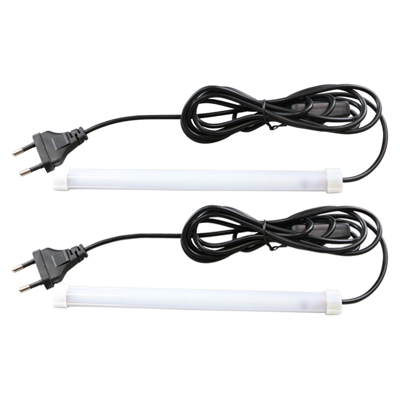
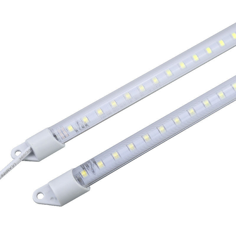
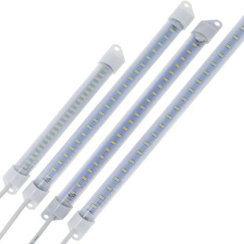
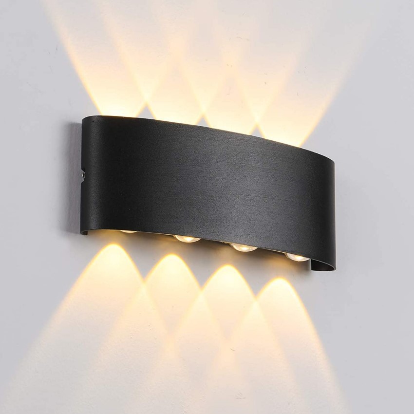
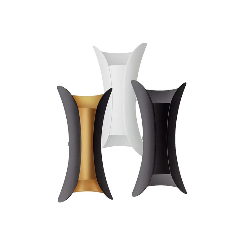
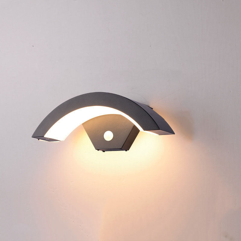
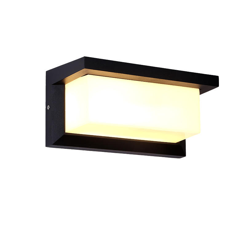
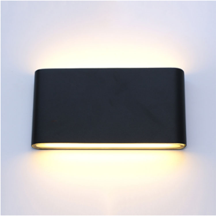
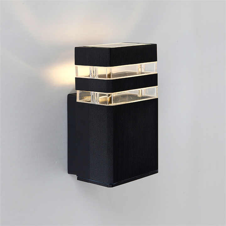
Lighting
As LED-based lighting solutions catch on in popularity because of their low power consumption and high levels of efficiency, so too does aluminum-backed PCBA which is used to make them. These PCBAs serve as heat sinks and allow for higher levels of heat transfer than a standard PCBA. These same aluminum-backed PCBAs form the basis for both high-lumen LED applications and basic lighting solutions.
Concept
After identifying the need for a PCBA, the next step is determining the board’s final concept. This initial phase involves defining the functions the PCBA will have and perform, its features, its interconnection with other circuits, its placement in the final product and its approximate dimensions. Also, consider the approximate temperature range the board will operate in and any other environmental concerns.
Schematic
The next phase is to draw the circuit schematic based on the final concept. This diagram includes all the information needed for the electrical components of the board to function appropriately, as well as details such as component names, value, rating and manufacturer part numbers. While you’re creating your schematic, you’ll be creating your bill of materials. This BOM contains information on all of the components you need for your PCBA.
Board-Level Block Diagram
Next, you will complete a board-level block diagram, a drawing describing the final dimensions of the PCBA. Mark areas designated for each block, sections of components that are connected for electrical reasons or because of constraints. Keeping related components together will enable you to keep your traces short.
Component Placement
The next step is component placement, which determines where you will place each element on the board. Often, you may go through several rounds of refining component placement.
First-Pass Routing
Next, determine the routing and the routing priority for the circuit.
Testing
After you’ve completed the design, you should conduct a series of tests to ensure it meets all your needs. If it does, the design is complete. If not, you will go back to the phases where you need to make adjustments.
Etching or removing excess copper from inner layers to reveal traces and pads
Creating the PCBA layer stackup by laminating (heating and pressing) board materials at high temperatures
Etching or removing excess copper from the surface layer(s) to reveal traces and pads
Imaging desired layout on copper clad laminates
Drilling holes for mounting holes, through hole pins and vias
Plating pin holes and via holes
Adding protective coating to surface or solder masking
Silkscreen printing reference and polarity indicators, logos or other markings on the surface
Optionally, a finish may be added to copper areas of surface
How to Choose a PCBA Board Size?

PCBA Sizes
Shapes: PCBA boards have several kinds of shapes. From circles to rectangles. From star square, many shapes are available. Hence, these shapes can help in reducing the size of the circuit. Tab routing or V-score has been used o cut the shapes.
Thickness: Thickness can affect the device size and cost. And the number of layers determines the thickness. For example, the six layer board require least thickness of 0.031″

Factors For Choosing a Correct Size
Weight: See the weight of the device for which you’re making the circuit. Don’t use a thinner board unless it got necessary for the required applications. Because the thinner board can get break easily.
Flexibility: Thick boards are heavier and less flexible. Thin boards are more flexible. However, they can easily get break. Use the board according to your required circuit. For instance, smart watches may need a flexible circuit while computer mother board needs a thick board.
Quality
Quality is a key issue when selecting the right PCBA manufacturer. It’s key that your design is delivered as required and to the defined specifications without errors in. The first question to ask is whether the (PCBA) Printed Circuit Board Manufacturer can work to the specifications you require. Use a detailed checklist to ensure they are able to meet all your criteria.
Cost
Cost is another key factor. Reducing costs is part of making a product successful, however but as had been said, the joy of a lower price,is forgotten long before the grief of poor quality has been overcome. Balancing cost and quality is essential to achieving success.
Timescale
Ensuring deadlines can be met is a major factor that should be considered when selecting a PCBA manufacturer. Short lead-times are great, but is a quick turn capability the right solution for longer term production?
Material Sourcing
Material sourcing is another key question for many companies looking at selecting the right PCBA manufacturer will be where the materials are sourced. Some low cost manufacturers may look to sourcing materials from the lowest cost source, and as a result the boards may not be consistent, varying in performance from batch to batch.
Production Capabilities
It’s worth matching the capabilities of the PCBA manufacturer to the likely quantities of printed circuit boards that need to be supplied for your program. It may be that prototype PCBAs are required and these will have very small quantities, or it may be that small production run quantities are needed before volume production is to start. Match the PCBA manufacturer capabilities to what is needed.
Our Factory
We have an independent factory and are able to provide competitive prices. Currently, there are 2 Sanyo high-speed placement machines, 2 Samsung precision placement machines and a full set of LED product testing equipment. The daily output reaches 20,000, and the order can be delivered in time.


Our Certificates
Our products are produced under a strict quality control system, comply with industry standards and have passed CE certification, and the defective rate will be less than 0.2%. The products are exported to more than 80 countries around the world and receive favorable feedback from customers.


Ultimate FAQ Guide to PCB Board
As one of the leading pcb board manufacturers and suppliers in China, we warmly welcome you to wholesale cheap pcb board in stock here from our factory. All customized products are with high quality and low price. Contact us for more details.